Nucleic acids extraction System
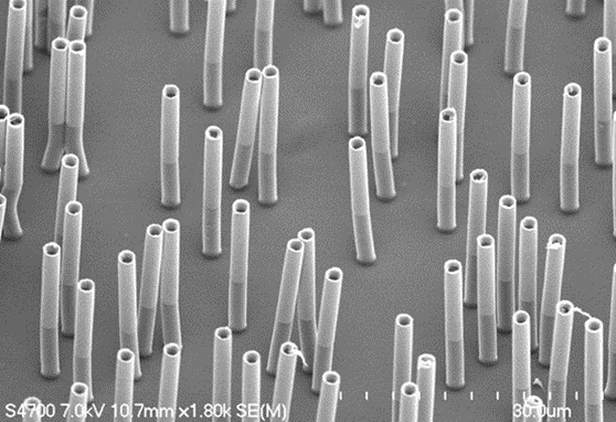
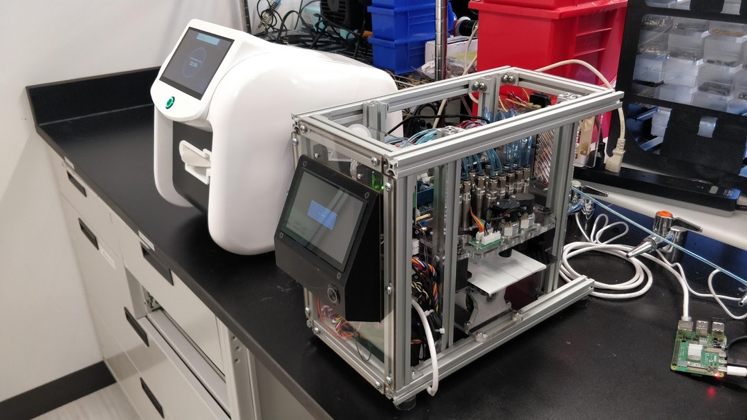
NAxtract is an innovative automation platform designed for rapid nucleic acids extraction assays, capable of processing up to eight samples in under thirty minutes. Microfluidic workflows often experience prolonged reaction times due to challenges in fluid mixing within low-inertia environments. Utilizing Redbud Lab's patented micro-post technology, NAxtract accelerates reactions significantly, surpassing diffusion time scales by orders of magnitude. These micro-posts operate similarly to numerous tiny stir bars, which can be controlled through a changing magnetic field. This groundbreaking technology enables the automation of industry-standard bead-based assays within a disposable cartridge.
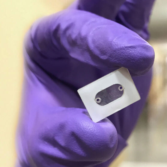
To achieve successful commercialization of this groundbreaking technology, Redbud Labs aimed to create the most reliable and user-friendly assay automation platform available. We refer to this as an automation platform because it has the potential to perform many different assay workflows in addition the the extraction assay that is runs now. Our project's objective was to provide needed automation for laboratories who normally do their extractions by hand. We noted that existing automation solutions were costly, bulky, complex, and unreliable.
Identifying a market opportunity, we established ambitious goals. Our device would cost one tenth of our competitors' prices and would not necessitate annual maintenance contracts. It would have a lifespan of 10,000 hours without the need for preventative maintenance, be compact enough to fit within a biosafety cabinet, and be the simplest machine to operate in the lab, designed with a single-button workflow that requires minimal user interaction.
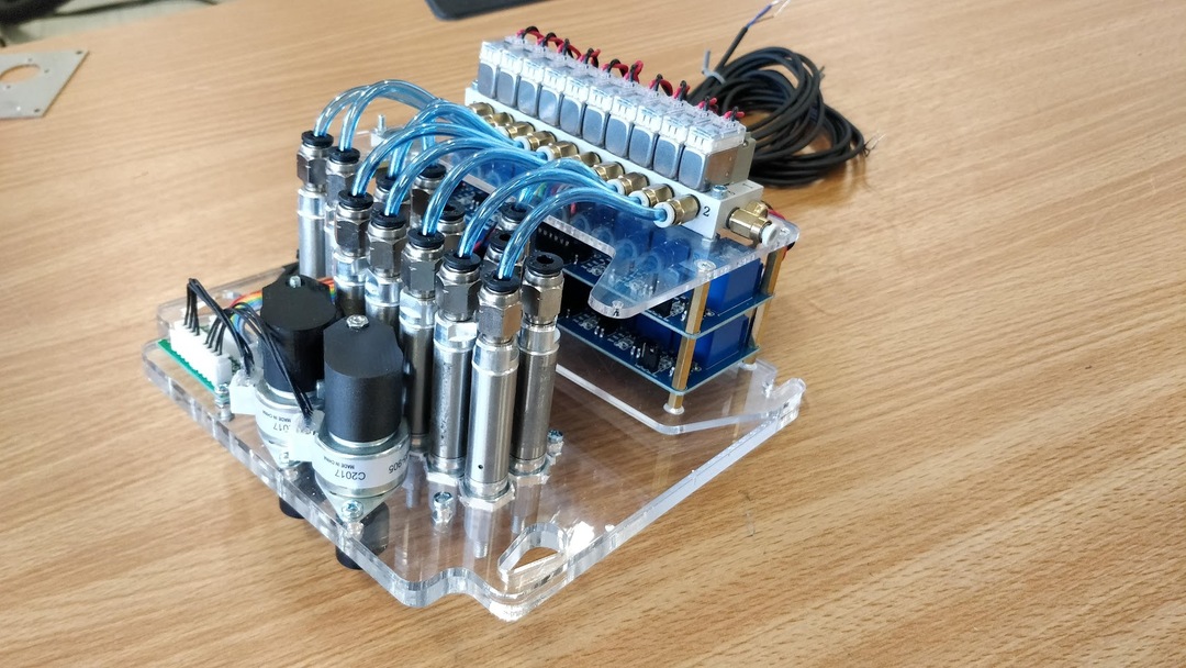
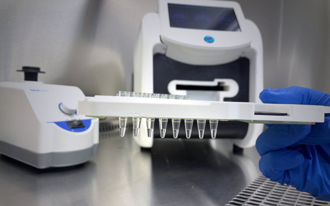
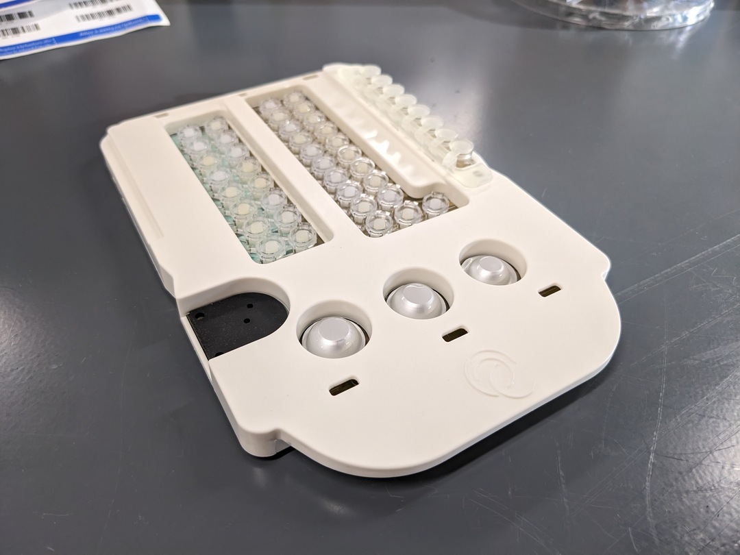
The instrument's function is to accept a microfluidic cartridge, inserted by the user, and to manipulate the internal fluids to replicate the steps of a manual extraction assay. The cartridge is pre-loaded with all necessary reagents, and the user adds up to eight of their own samples to the designated wells. The instrument precisely heats the reaction chamber on the cartridge and utilizes low-pressure air to circulate fluids within the cartridge. Both waste fluids and purified nucleic acids are retained in the cartridge, which is removed by the user. The extracted samples are recovered in PCR tubes and the cartridge, with the waste fluid inside, is disposed of.
As the lead design engineer, I was responsible for taking a benchtop prototype through multiple design iterations before transitioning to production with contract manufacturers. This project presented some familiar obstacles along with new challenges grew my engineering skill set. I worked to not only developed a novel laboratory device, but also create a robust library of components and methods used to interact with the microfluidic cartridge. Moving forward, we will be able to quickly adapt entirely new assay workflows to a similar instrument and cartridge setup.
Accurate thermoplastic Material Feed
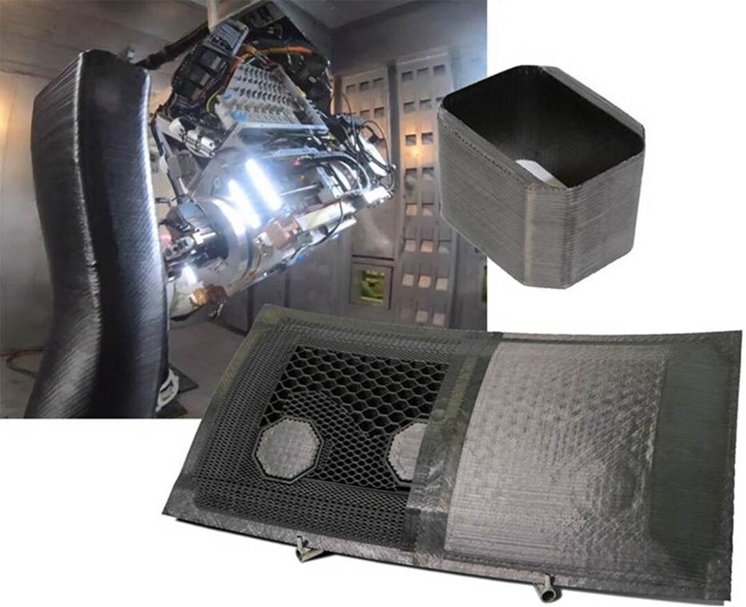
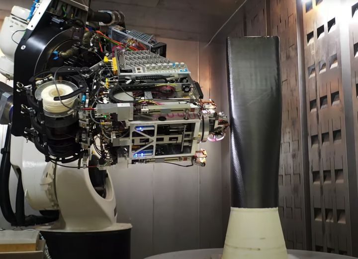
Electroimpact's Scalable Composites Robotic Additive Manufacturing (SCRAM) system is a true 6-axis continuous fiber reinforced 3D printer, enabling the tool-less rapid fabrication of aerospace-grade integrated composite structures. High-performance thermoplastics combined with a high percentage of continuous fiber reinforcement are used to produce parts with exceptional mechanical properties previously unheard of in the world of 3D printing.
The SCRAM system uses three separate process ends for building composite structures. Two of these are heated filament extruders, much like what you would see on a hobby 3d printer. The third is a tape laying system used to bond continuous fiber thermoplastic tape to the structure. Each of these processes requires a different material to be dispensed. An ABS-like material is used for printing a tool a tool that the composite structure will be build on. The other two materials are thermoplastics, one is a round filament for extruding and the other is a tape.
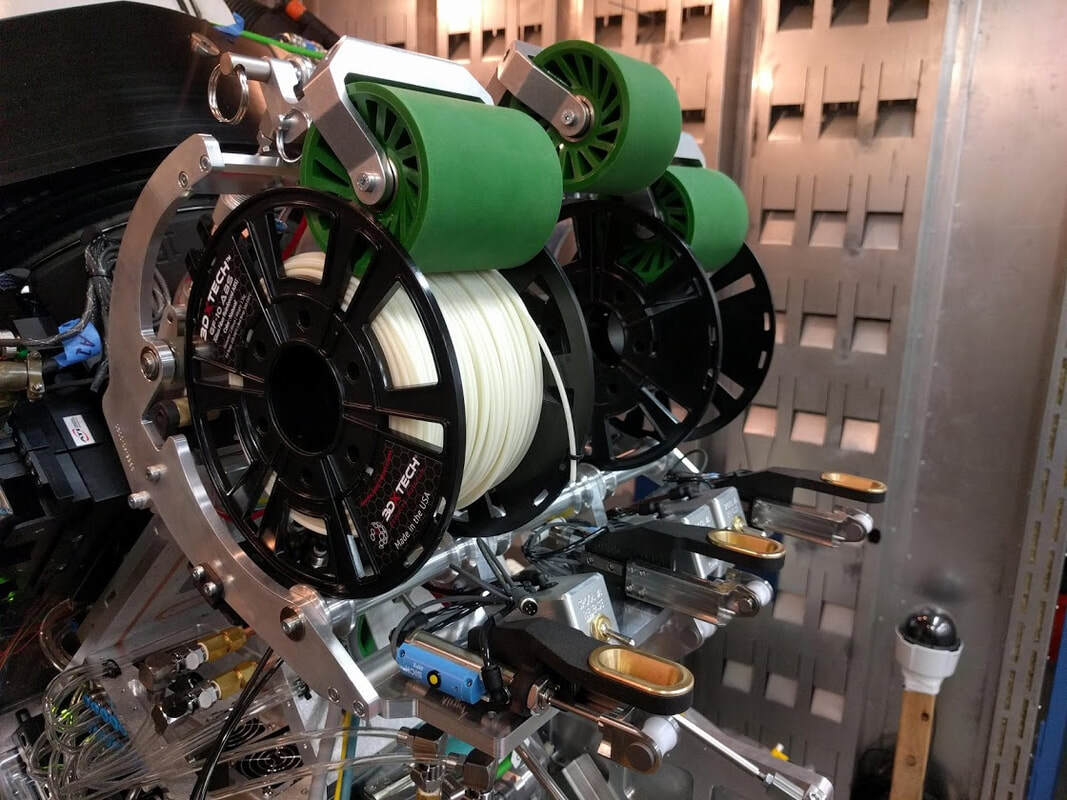
I designed a material storage and accurate feed system to meet the unique requirements of the SCRAM system. This assembly needed to mount onto the process end effector, store three different materials, be able to change material spools quickly, actively pay out the material, and select which material is to be dispensed.
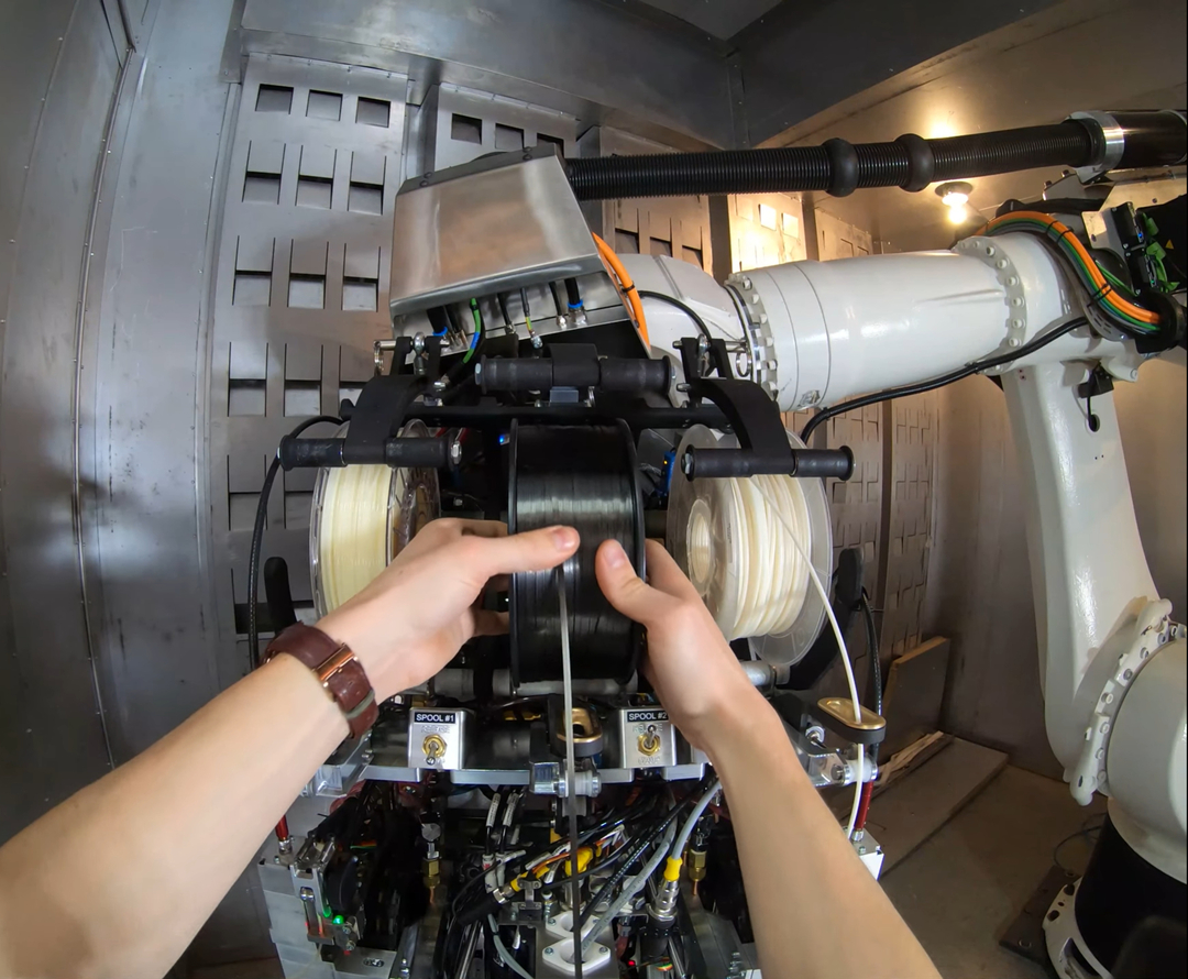
Being able to quickly change the materials was important to this project because the large aerospace structures that this system was designed to create require much more material than a typical 3d printer. While the spools of material resemble what you would see on a typical extrusion printer, they are widened to hold more material and still a single print will use several spools of material. On other printing systems these spools are often dispensed from some sort of shaft that runs through the center of the spool. having a center shaft would make removing and adding spools difficult. Instead, I designed a pneumatically driven arm an roller which secure the material in place and allow for the spools to be changed one at a time. The user toggles a pneumatic valve to select the position of the roller arm. The roller contacts the material itself to keep the spool wound tight during operation.
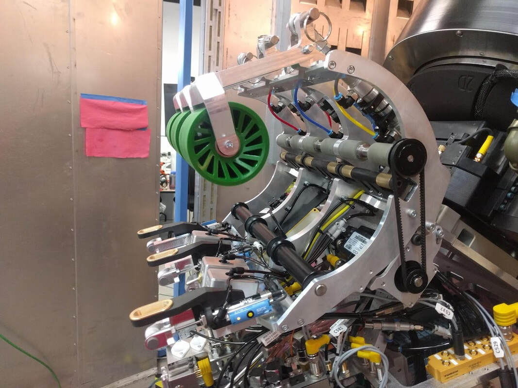
The material feed assembly must actively dispense the material as it is being used. During a print, only one material is used at a time and the other two are idle. I designed a method of dispensing only the chosen material using a single servo motor and three guided air cylinders. The servo motor turns a belt driven shaft that run along the back side of the three spools of material. The shaft has six urethane rollers which contact the rim of the material spools. Bellow the drive shaft are three guided air cylinders with brass rollers that can contact the rim of the spools when the cylinders are extended. Doing so pushes the spool off of drive shaft. The spool is able to move a small and still be securely held in place because the force of the selection cylinder can overcome the force of the roller arm. By extending two of the the selection cylinders and retracting the third, only one material spool contacts the drive shaft so that one can be dispensed.
When the SCRAM system is building a part, it must accurately dispense the correct quantity of material for each length of the toolpath. The process ends of the system have their own feed mechanisms which grip the material and drive it into the extruder or tape laying ends. It is possible to leave the spools of material free spinning and allow the process end feed to drag the material our of the spool. This creates reliability problems because the material is more likely to get jammed or slip due to added tension in the material.
I designed a feed system which is slaved to the process end feed by measurement of tension in the material. When it is time to dispense material the process end pulls on the material which increases tension in the line and will move a small air connected to a roller that touches the material. based on the position of that air cylinder the spool of material is advanced or reversed to keep consistent tension in the line. The video bellow shows this slave mechanism in action. It is hard to tell exactly what is happening in this video without some explanation. off-camera a person is pulling down on the material, or releasing the material. The small measurement air cylinder mentioned can bee seen towards the bottom of the frame. The spool of material rotates in both directions to either feed out or return the material to the spool.
Automated Fiber Placement
An Automated Fiber Placement (AFP) head is a piece of aerospace manufacturing equipment used to deposit uncured composites onto a mold. The AFP heads carry spools of material ranging from 1/8” wide to 1/2” wide tapes. Each head contains its own electrical, pneumatic and controls system and can be mounted to a gantry machine or industrial robot arm.
I worked to design and improve mechanical systems on the creel and the process ends of these end effectors. I also worked to support legacy AFP heads used in production facilities around the world.
Because of each customer’s unique application, each new project involves a large amount of design changes to these heads. I lead a team of six engineers to create a new AFP head for the National Composite Centre (NCC) in Bristol, UK. This project involved adapting the widest format material (1/2”) to the smallest head format (8-spools) in order to fit the head inside a female tool. The NCC also required the integration of a xenon flash lamp heater in addition to a standard infrared heater.
In order to meet these specifications we needed to design an almost completely new head. My team and I took advantage of this opportunity to correct many constraint problems and inconveniences which persisted on older AFP heads. After completion, these designs were quickly propagated to four new projects for other customers and have become a standard offering for Electroimpact.
In addition to design work, I was responsible for some aspects of the construction and commissioning of AFP systems. Troubleshooting the problems seen on this equipment requires intimate knowledge of the mechanical, electrical, pneumatic, and controls systems and how they interact with each other. Through many cycles of design, testing, delivery and support I have learned how to better design for the whole life cycle of a product.
Robotics Controls and Programming
The Automated Fiber Placement (AFP) heads and Kuka robots I worked with are controlled with Seimens PLCs, CNC, and a custom built HMI. As an engineer working on the development of the AFP heads, one of my responsibilities was to commission and test the entire AFP system before it was sent to the customer. This commissioning involved setup of the robot's CNC and PLC, setup of the head's PLC and integration of new equipment into the controls system.
For example, one of the AFP heads I designed featured a new infrared heater design along with new current regulators to power the heater. To insure consistent heat was applied to the carbon fiber tape at a variety of different running speeds I had to characterize the heat output of the four separate infrared emitters. I did this by correlating the commanded power to the current regulators, to the temperature of the carbon fiber, measured with thermocouples, at a variety of different speeds. This experiment gave me the desired power command at each speed. With that knowledge I wrote a PLC function which controlled the heaters output based on the speed of the robots tool point.
End Effector Stands
One important feature of AFP systems is that the end effectors can be quickly placed into a stand and exchanged for a different end effector. Some of these stands move or rotate the end effector for operator or maintenance access.
I have designed several of these stands for different end effectors. In general, the stands consist of large steel weldments which are anchored into concrete. The weldments are built from tube steel and brake formed steel sheet. The sands need to repeatably locate the end effector for pickup and drop-off.
For one project I designed a stand which would lift a 1,500lb end effector to a position where it could be picked up by a gantry machine. My design uses a servo driven acme screw to lift the end effector. Linear rails and bearing cars were used for accurate and repeatable positioning. The structure was required to withstand a strong earthquake without falling over.